
The controller was designed to work with the car roof rack-mounted satellite antenna system (a separate project), but can be used with any other design based on the supported rotator hardware.
The first version of the controller supports Alfa Radio rotator, model RAU only, performing horizontal rotation of the antenna system. For satellite use the fixed elevation technique can be employed. It is expected that the future versions of the controller could control the elevation antenna mechanism as well. The following functions are provided by the controller:
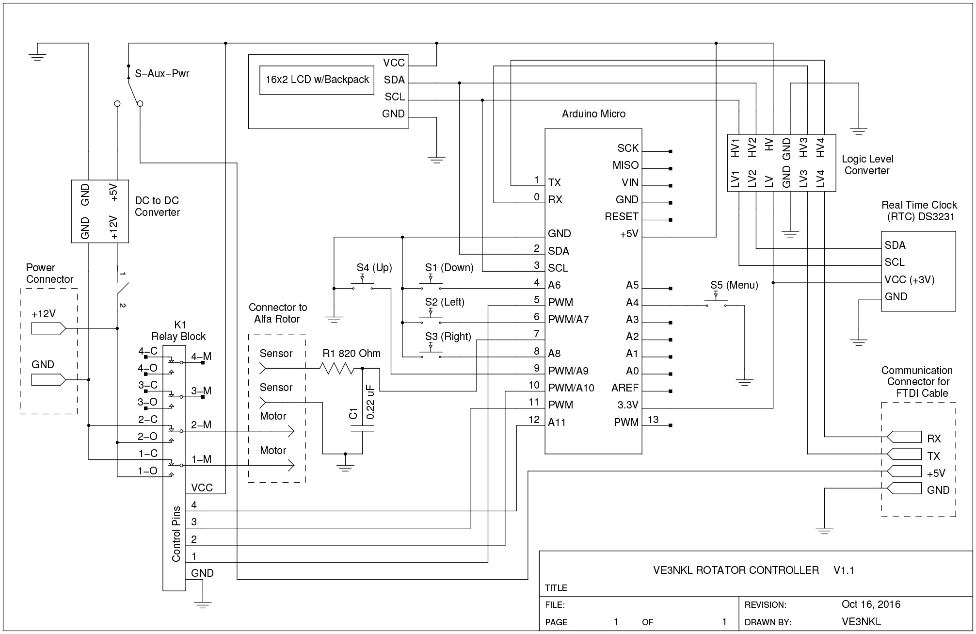
The controller is based on the Arduino Micro Pro board, 16Mhz version. It also has a DC to DC down stepper to convert power from 12V DC to 5V DC. A Relay block controlled by the microprocessor is used to control the rotator. There is also a quartz-stabilized clock board for keeping accurate time (with an accuracy of less than a second per day). It communicates with the Arduino microprocessor using the I2C interface.
A 20-character 2 line display (40 characters in total) is also connected to the I2C bus. 5 buttons (4 on the front panel and the menu button on the back panel) are also connected to the Arduino board.
In addition to the mentioned above components the logic level converters were used where it was necessary to connect the circuits using 5V and 3.3V TTL logic. Note a RC filter at the sensor input. This input is used to read pulses from the rotator. The purpose of the filter is to reduce jitter noise coming in from the rotator. This issue also exists for the buttons, but their state is polled on a regular basis and, therefore, the jitter noise generated by them can be dealt with in the software. As for the rotational sensor, its contacts are used to trigger an interrupt in the microprocessor. To avoid multiple interrupts occurring in a small fraction of a second, a simple RC filter was used. The rest of the schematic is self-explanatory.
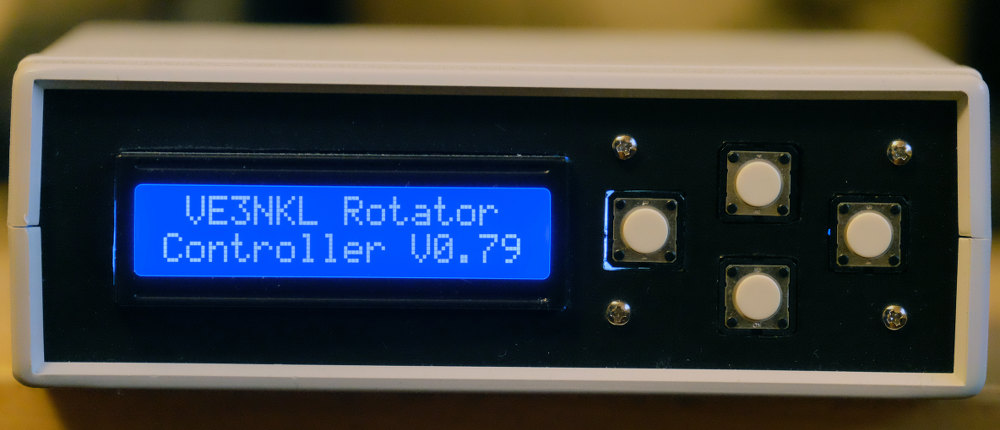
The front panel has 4 control buttons (left, right, up and down). In the manual control mode (shown on the picture) the left and right buttons are used to rotate the antenna counter clock-wise and clock-wise correspondingly. The up and down buttons are not functioning in this mode but might be used in the future versions for the elevation control. All 4 buttons are used in the menu mode. In this mode the left and right buttons are used to switch between menu choices on the current menu level and the down button selects the desired choice. The up buttons acts like a backwards button in the menu mode. The same buttons can be used to change numeric values of some parameters in the menu as well (the initial antenna azimuth, for instance).
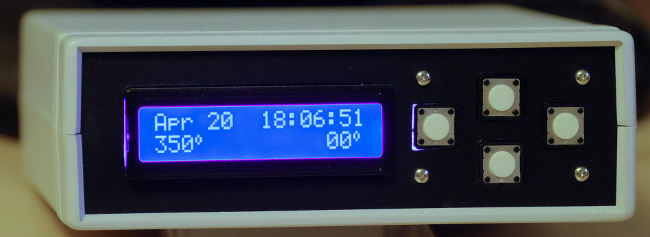
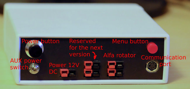
All connection sockets of the controller are located on the back along with some additional controls. Normally, the controller is powered by a 12V DC source. It is used to power the electronics of the controller and the rotator. Although, when you upload pass information from your PC to the controller, it could be more convenient to power the controller's electronics from the PC's USB port, without using 12 V DC power supply or battery. This can be done by switching the AUX power switch to ON. A special cable is used to connect PC USB port to the controller's communication port. A rotator is connected to the controller using a 4 wire cable. Two wires are used to carry 12V power to the rotator and the other two are used to read the pulses generated by the rotator for every degree of its rotation. Another 4-pole socket is not presently connected anywhere and is meant to be used in the future versions of the device for elevation control.
The software for the controller was written in C using Arduino SDK. One of the libraries (the one providing an interface to the Real-Time clock module) was updated to better suit the needs of this project. To view the controller source code click the icon on the right. The biggest challenge was to make the code as compact as possible due to the choice of the Arduino board. To do this, the embedded boot loader had to be removed to free some additional space. Uploading the code now has to be done by using an external programmer.